A Stable Regenerative Receiver
The YooFab Ceramic Resonator Regenerative Receiver For The 40 Meter Band#
Want To Just Get On With Building?#
For those of you that just want to get on with building the project, you could skip all the following content and jump down to The Section headed Building The Project.
However, you are advised to read all the content on this page, as it is here to help you.
Please read Check Everything First before doing anything.
Introduction#
The following briefly describes the key advantages of this regenerative shortwave receiver:#
- This is a very good portable regenerative shortwave radio for the whole (international) 40 meter HAM radio band (just below 7 MHz to 7.35 MHz.)1
- It is easy to build and works very well.
- It is able to receive AM, SSB, CW and other modes.
- It runs on a 8 x 1.5 Volt AA battery pack, which should be available shortly from our shop.
- The receiver is small enough to put in your coat pocket and light, yet powerful enough to receive weak DX signals.
- It has a switchable Oscillator output 3 Volt p-p square wave buffer. This is intended to be used for an external frequency counter.
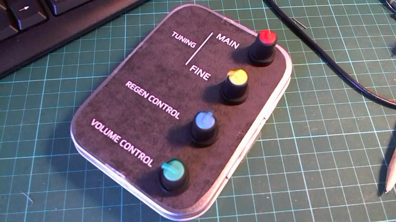
- All controls, Antenna, Audio & frequency counter output are available from the front panel.
- This is a complete project; when built it is a receiver that is durable, can be carried anywhere.
- The receiver is fun to use and once you are familiar with how to drive it, you will be amazed at what this little receiver is capable of.
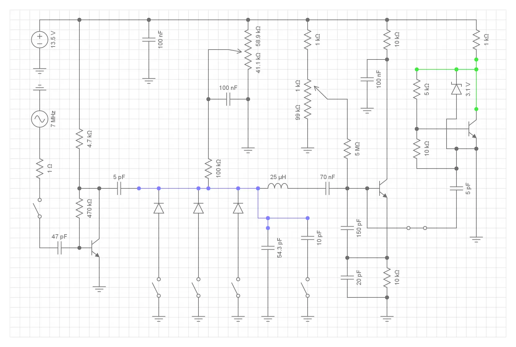
This receiver has a tuning range of just below 7 MHz to 7.35 MHz. Thus, it tunes the whole 40 meters band including the USA version of the band, which in some parts of Europe is dominated at the top end by intriguing Chinese Broadcasting. INCREASED coupling Cap from 5 pF to 10 pF and then lowered it again to 5 pF. Here shown as a schematic that is as near to the prototyped version as possible. (WARNING! No Xtal or Resonator device on EC! This simulation therefor uses a coil and adjusted caps in the colpitts oscillator) The resonator is shown as a 10 nF capacitor.
Performance#
The receiver is an excellent performer allowing the reception of AM, SSB, CW & Digital modes:#
-
High selectivity, sensitivity & stability (due to the ceramic resonator) and the regenerative design.
-
The selectivity and filter shape can be controlled using the regenerative adjustment. This can filter out AM signals or allow you to concentrate on CW or SSB.
-
You may use a simple one or one and a half meter length of flex wire as an antenna (aerial), which you will find to be more than sufficient.
-
Low power - even with the headphone amplifier the receiver only uses about 16 mA!
-
The project currently does not includes an on-board headphone amplifier. However, this is easy to fix.
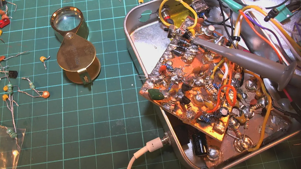
This design is the result of hours of experimentation, spent building and modifying circuits soldered onto copper clad board using 'Dead Bug', 'Messy' or 'Manhattan' style prototyping technique. The basis of the experimentation is a closely guarded secret only available to YooFab converts.
The Background Of Regenerative Receivers#
The Armstrong Regenerative Receiver#
The picture below shows a homemade single tube Armstrong regenerative shortwave radio receiver.

The regenerative receiver was invented in 1912 by Edwin Armstrong. The tube regenerative receiver design was abandoned by commercial radio manufacturers in the late 1920s due to its tendency to radiate interference. However, its simplicity and low cost resulted in the continued use of the design by radio amateur radio constructors for shortwave listening.
The Armstrong circuit features the 'regeneration' or feedback being provided by a "tickler" coil connected to the plate circuit of the vacuum tube which is coupled to the tuning coil in the grid circuit. The tickler coil is visible as a variometer winding within the vertical tuning coil, mounted on a shaft which could be rotated by a knob on the front panel to adjust the feedback.
The Yoofab Regenerative Receiver Does Not Use A Tickler Coil For Regeneration#
The YooFab regenerative receiver does not use a tickler coil for regeneration. Instead it uses a capacitive divider circuit that is part of the Colpitts oscillator design.
Very low emission#
The current design avoids the tendency to radiate interference that was a feature of the Tube (Valve) Armstrong designs. This is achieved by the front end amplifier/ buffer stage.
How Was This Receiver Developed?#
My style of prototype build is not really Manhattan. It is Authentic Messy Construction Technique (AMCT) using punched circular and strip shaped lands that are cut from old copper clad board. This works well. I recommend this build technique; it's a good way to make things with Radio Frequency Electronics (RF) and indeed with almost any circuitry.
A Brief Description Of The Development And Prototyping Method.#
Thee following list of 5 key points relates to the development method used. The list is not exhaustive and is better dealt with elsewhere on this site.
- Simulate the circuit using SPICE and/ or other tools. This gets you more than half way toward having a working design before building anything. It also lets you see potential issues and improvements before committing to a particular solution.
- Build it first using a layout that is as close to the circuit diagram as possible. (one of the prerequisites of this, is to layout the circuit diagram clearly following some simple rules) I use DIYLC which is a cross platform layout software that's ideal for prototyping using Manhattan, dead bug or Authentic Messy Style.
- Test & modify it until it's working according to your desired requirement specification. (here you do need to resist too many temptations of expanding the scope of your design, which is often difficult)
- Revisit the simulated version with any updates to the schematic.
- Build yourself the neat version (if you ever get around to this - in practice it may be just as easy to take this directly to PCB manufacturing)
Circuit Description#
Overview#
The receiver is designed to be highly portable yet very sensitive. It is fixed band; this design is centred on the 40 meters or 7 MHz band, which is controlled by the choice of resonator used. Equally, a 3.5 MHz resonator could be selected and this would correspond to the 80 Meters band.
This is the electronic schematic diagram for the YooFab regenerative receiver.
To see a bigger version of the schematic, right click on the diagram and choose 'open image in new tab' or other options depending on your browser
Explanation Of The Circuit Functionality#
Even Though Its Simple The Result Is Far From Rudimentary#
Even though the receiver is very simple, the result is far from rudimentary and is capable of world-wide reception at high sensitivity. It uses only a maximum of a two meter length of wire as an antenna and should never be used with a big HAM radio antenna. Doing this will swamp the sensitive circuitry with too much signal. The result will be a horrific cacophony of all stations especially the strongest ones. There is no Automatic Gain Control (AGC), as this is not really needed with this type of receiver when the correct antenna is used.
The First Stage#
The first stage, is a simple wide band RF preamp. The signal is fed into the second or regenerative stage; this is essentially an oscillator that is both frequency controllable and has a control over the feedback (regeneration which is what Armstrong called it).
The Second Stage#
The second stage is the main engine of the receiver, functioning as frequency discriminator, filter, oscillator and even beat frequency oscillator. Because this stage is essentially an oscillator, it acts as an amplifier with a potentially huge gain at the selected frequency.
The Buffer Squaring Output Stage For External Frequency Counter#
This is a simple one transistor buffer that is biased such that the output is clipped. In this manner it produces a square wave +3Volts that should be suitable for most frequency counters. You will note that there is a zener diode, which acts as a voltage shifter and clipper.
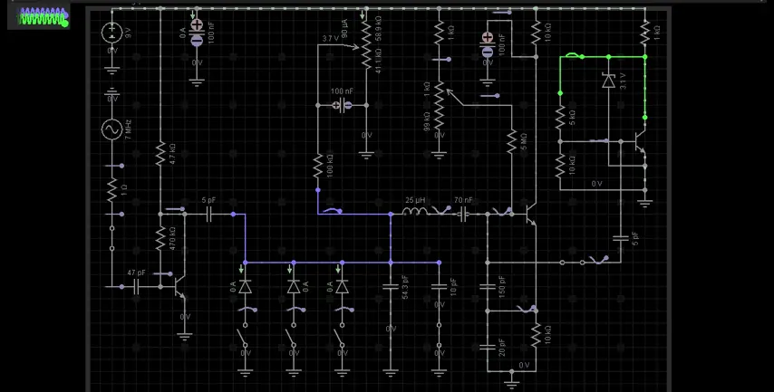
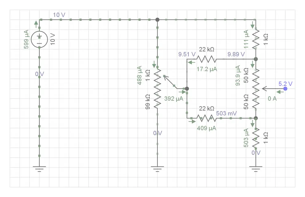
A Simulation Of The Circuit#
This shows a version of the circuit with voltage regulation.

This version shows a version of the circuit where the voltage regulation to 9 Volts is assumed to be already on-board.
The Resonator#
As explained, this circuit makes use of a ceramic resonator which is NOT shown on the schematics that you have seen so far. This is because the chosen simulator does not have a ceramic resonator component. However the 7.37 MHz resonator goes where the 70 nF capacitor is shown.
The receiver is designed to be a coil free radio. (only in the sense that no coils need to be wound)
The Tuning Mechanism#
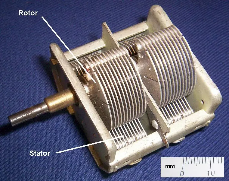
A Traditional Air-Spaced Variable Capacitor#
This is a picture of a relatively small air-spaced capacitor. However, even this would occupy too much space inside the case of the regenerative receiver.
To see a bigger version of the schematic, right click on the diagram and choose 'open image in new tab' or other options depending on your browser
The tuning mechanism of this radio receiver does not use a traditional variable capacitor.#
This is because such capacitors are in short supply, expensive and large. For this reason, I used 1N4007 rectifier diodes. These are employed as a Varicap diodes.
One of the prerequisites to allow such simple rectifier diodes to be used as capacitors to pull the frequency of the resonator over the whole of the 40 meter band, is a specialised oscillator design. This subject is dealt with in detail elsewhere on this site.
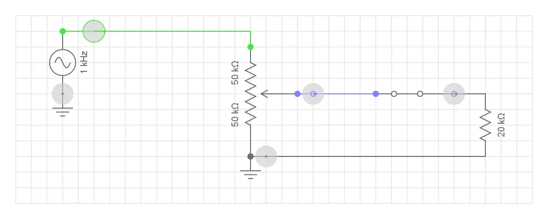
The simple one potentiometer control, seen in the schematic above, is actually implemented as a two pot rough and fine tuning control arrangement which you can see in a diagram below.
To see a bigger version of the schematic, right click on the diagram and choose 'open image in new tab' or other options depending on your browser
This Varicap arrangement works very well and provides a few KHz fine tuning. I chose a 20KΩ pot to supply the variable voltage to the top of the diode. No big deal, any value below 100KΩ and above 10 KΩ will work here. A linear taper should be used.
The original idea for the resonator regenerative receiver was from VK3YE an Australian HAM radio enthusiast and electronics mega-boffin. In his YouTube videos, he describes a number of versions of this circuit running from 12 volts, as is the norm with most QRP (low Power) HAM radio circuitry.
Updated Regenerative Control#
After some use and a check of other designs, I modified the resistors around the regeneration pot. The 1 MΩ resistor between the base of the oscillator and the wiper of the pot is now increased to 5 MΩ. (lets about 100 - 150 nA pass). Also the top lug of the 100 KΩ pot is now fed by a 270 KΩ resistor. This presents just above 2.5 Volts to the top of the pot.
The volume control#
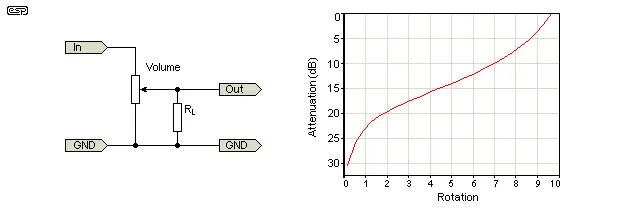
As Log & Audio taper pots are now becoming hard to acquire, the following circuit is used. This is actually better as a volume control than the average log tapered pot.
This circuit diagram shows how to convert a linear potentiometer into a log-style pot.
To see a bigger version of the schematic, right click on the diagram and choose 'open image in new tab' or other options depending on your browser
Changing the Law of a Pot#
Taken from Change the law of a pot which is on the excellent Elliott Sound Products website
"The volume control in a hi-fi amp or preamp (or any other audio device, for that matter), is a truly simple concept, right? Wrong. In order to get a smooth increase in level, the potentiometer (pot) must be logarithmic to match the non-linear characteristics of our hearing. A linear pot used for volume is quite unsatisfactory unless you give it the resistor treatment"
"Unless you pay serious money, the standard 'log' pot you buy from electronics shops is not log at all, but is usually comprised of two linear sections, each with a different resistance gradient. The theory is that between the two they will make a curve which is 'close enough' to log (or audio) taper. As many will have found out, this is rarely the case, and a pronounced 'discontinuity' is often apparent as the control is rotated."
"As with all pots used as volume controls, the first 10% of rotation causes a very large variation in level (essentially from 'off' to quietly audible). A 'true' log response over the full range of perhaps 100dB is not really useful, because most of the time the gain is varied over a relatively small range. 25dB of variation is a power ratio of 316:1 - this will normally be the range over which any volume control is used."
So if you add a resistor as shown the the diagrams at a value of about 20% of the linear pot value, the problem is solved!
Building The Project#
Please follow these instructions very carefully. Doing so should prevent errors and should also ensure that you have a working Shortwave Radio Receiver.
Also, for the impetuous and those that must 'just get on with it', please do at least glance over the above circuit description before commencing the build. At the very least you may discover something you did not know... Or you might find an error on my part... at which point I ask that you email me ASAP.
Thank you for buying the project & good luck with the build.
Check Everything That Arrived First#
- Make sure you check all the project components that have arrived against the list given below under the heading Bill Of Materials below
- Make sure you have a clean workbench, desk or other suitable table surface to build this project and that you know how to use a soldering iron, hand tools, multimeter and other recommended items before commencing on this journey.
- It is well worth organising the electronic components by pushing them into a small piece of expanded polystyrene foam. You should label each component. (please see picture below)
Bill Of Materials#
Electronic Components#
- 3 x transistor BC-1234
- 5 x diode 1n4148
- 4 x diode 1n4007
- 10 x ceramic capacitor
- 12 x resistors various
- Ceramic resonator
- 2 x 100K pots
Other Items#
- A very nice tin
- A black printed circuit board (PCB)
- Other things
FOOTNOTES#
-
The 40 meter band provides unique opportunities for long-distance communication, making it a favorite among amateur radio enthusiasts. ↩