How to wind bifilar toroids
title: Winding Toroidal Transformers author: "Geoffrey David Cowne - M0OOZ" date: 2023-10-04 summary: "Detailed guide on how to wind bifilar toroidal transformers, with step-by-step instructions and images." tags: [bifilar, toroid, transformer, winding, electronics]
Winding Toroidal Transformers#
A bifilar transformer is an electromagnetic coil featuring two parallel, twisted windings. The term "bifilar" means 'two threads', referring here to the two strands of wire.
Important#
Toroids can be wound in both clockwise and counter-clockwise directions. In this example, you will wind counter-clockwise!
First, you twist the wires together. Below is a series of images demonstrating how to wind a ten-turn bifilar transformer. Unlike the typical black FT50-43 toroid used in many YooFab circuits, this example uses a larger green toroid. The sequence also features red and white wires, enhancing visibility and clarity of the winding process.
Preparation#
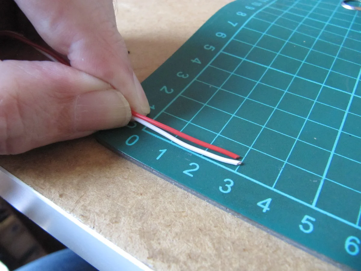
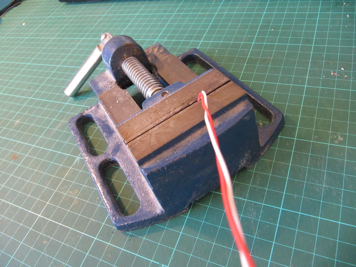
You will begin by preparing for the winding process. The first step involves marking the pigtails so that you have approximately 3 cm of wire (about 1.2 inches) to serve as leads for your transformer. In the next step, these pigtails will be placed in the vice.
Step one#
Place the two strands of wire together. In the picture below, you can see the two differently coloured wires. However, the solderable enamelled wire you will use will be the same copper colour for both strands.
Note that when winding with solderable enamelled wire, you do not need to cut the wire into two pieces. Instead, you can simply ‘fold’ the provided length into two strands, side by side.
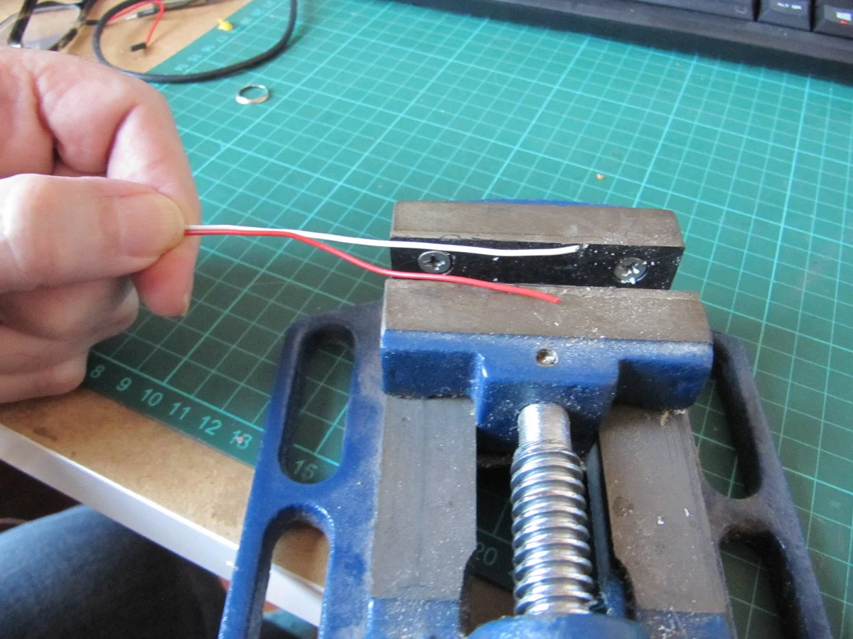
Clamp both strands of wire. Here, a vice is used. However, if you do not have a vice available, you can improvise with any tool or setup that can securely hold the wires while they are being twisted together.
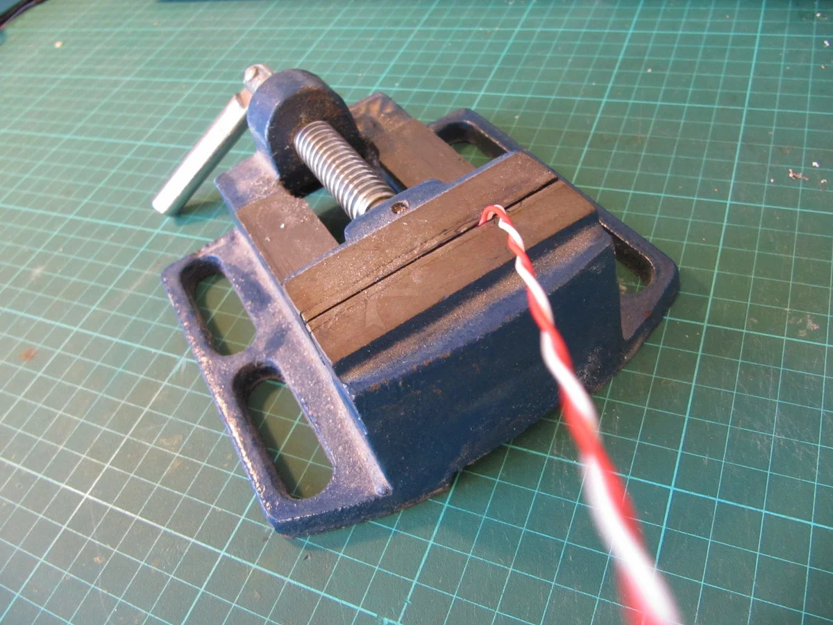
Step two#
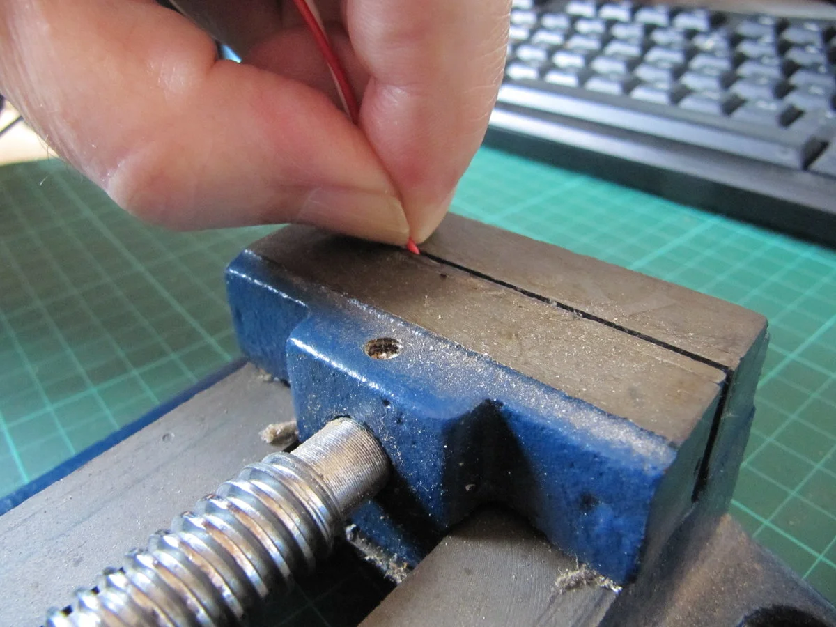
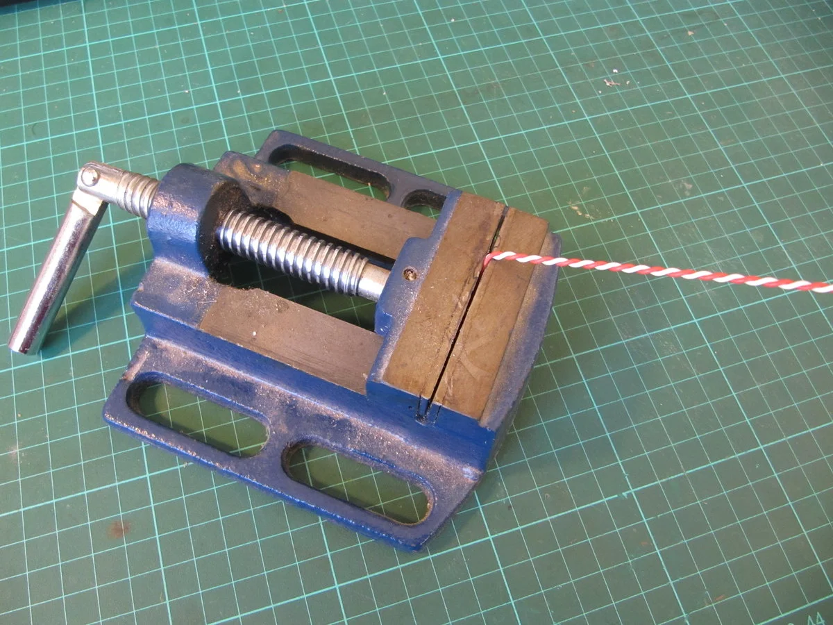
You now need to clamp the pigtails; you will need to clamp the whole 3 cm length of wire. Since the wire ends are entirely held in the vice, you will have leads that will serve as leads for your transformer.
Step three#
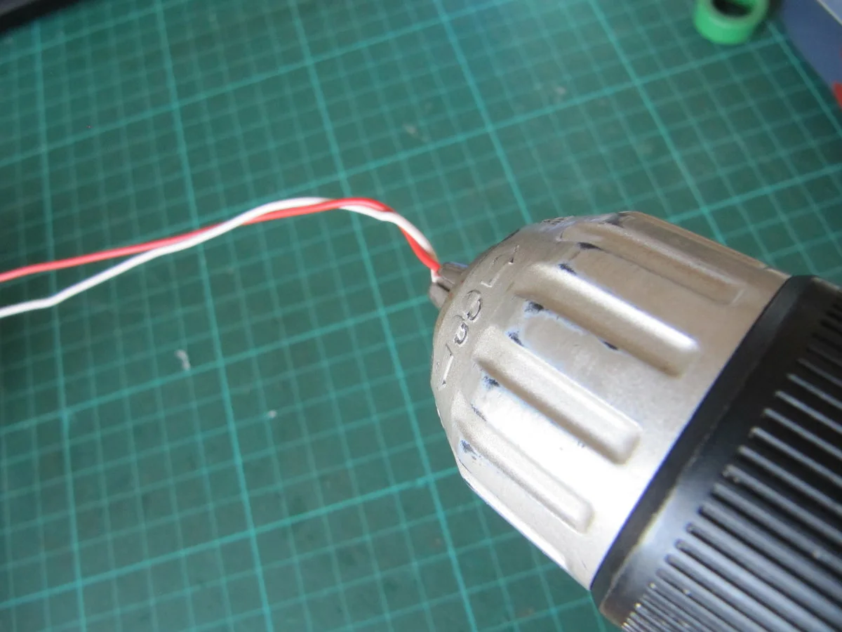
Put the other end of the pair of wires into the chuck of an electric screwdriver or an old-fashioned manual drill. Both tools have their advantages; a manual drill is easier to control, since the winding speed is literally in your hands. An electric screwdriver is faster, modern, and will get the job done quicker. You do need to have acquired practice with either of these tools. When it comes to an electric screwdriver, you need to have mastered the control of this tool. It can wind very fast, which could result in total disaster if you haven't got it under control.
Step four#
Begin winding the wires together. In this example, an electric screwdriver is used. Ensure you maintain control over whichever tool you choose for winding. Exercise restraint during this process; the wires are enamel-coated and fairly thick at 0.58 mm, approximately 24 SWG or 23 AWG, making mistakes costly. Unwinding these wires would be a tedious and unpleasant task, that you should aim to avoid.
Step five#
Just keep winding
Step six#
You should aim for windings that are about 7–8 twists per inch, OR about 3–4 twists per centimetre. Do not get fazed by this. The exact number of twists per centimetre is not that important. Since you are using a hand drill or electric screwdriver, the consistency of windings per centimetre will be almost entirely assured.
Step seven#
Detach your bifilar windings from the chuck and the vice. This leaves you with a perfect pair of wires to use in the next process. You will then have what is required to put these windings onto a toroid.
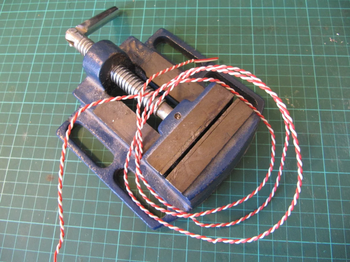
Step eight#
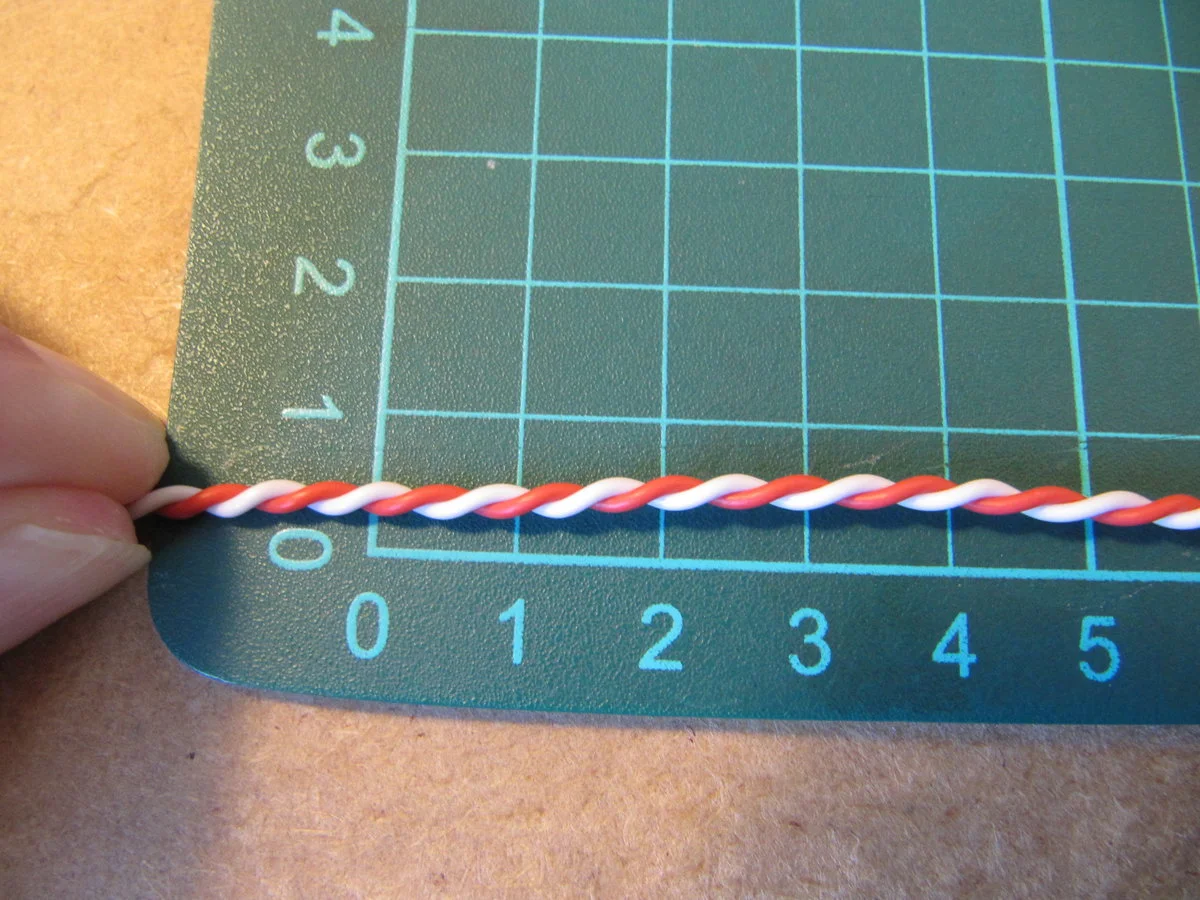
Here you assess the number of twists per centimetre. In the photograph below, you will see that there are approximately 3 twists per centimetre. The fact that the wire in the example is thicker and contains plastic insulation does not imply that the number of twists per centimetre should alter with a different type of wire.
It is always possible to wind more, however, removing twists per centimetre from the twisted pair is more challenging, albeit feasible.
Step nine#
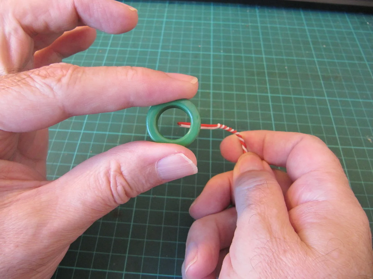
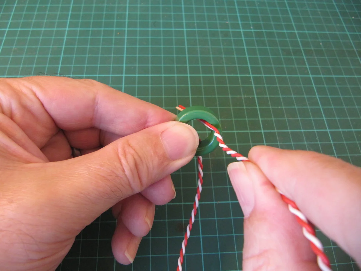
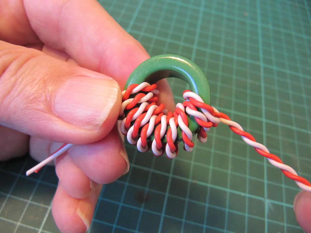
You are now ready to start winding the toroid. The following instructions assume that you are right-handed; this can all be reversed for those who are left-handed.
Choose one end of the twisted pair and hold this with your right hand. Now push the chosen end UP through the toroid.
Step ten#
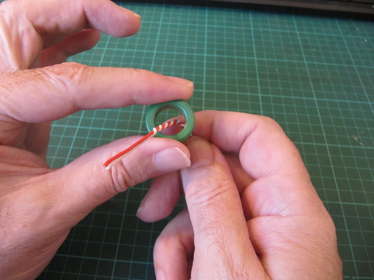
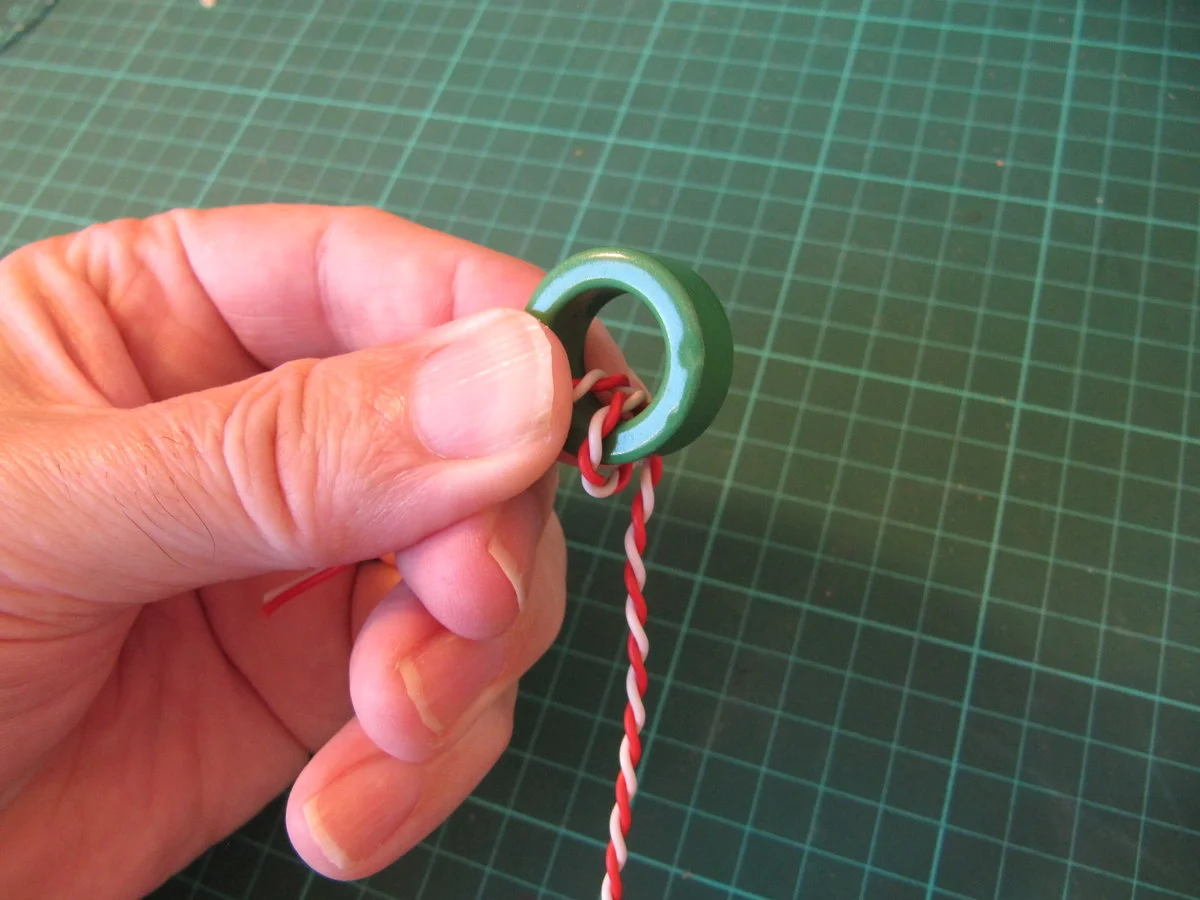
Below, you will see the twisted wire passing through the toroid. This counts as one turn. Remember: right up through the toroid.
Step eleven#
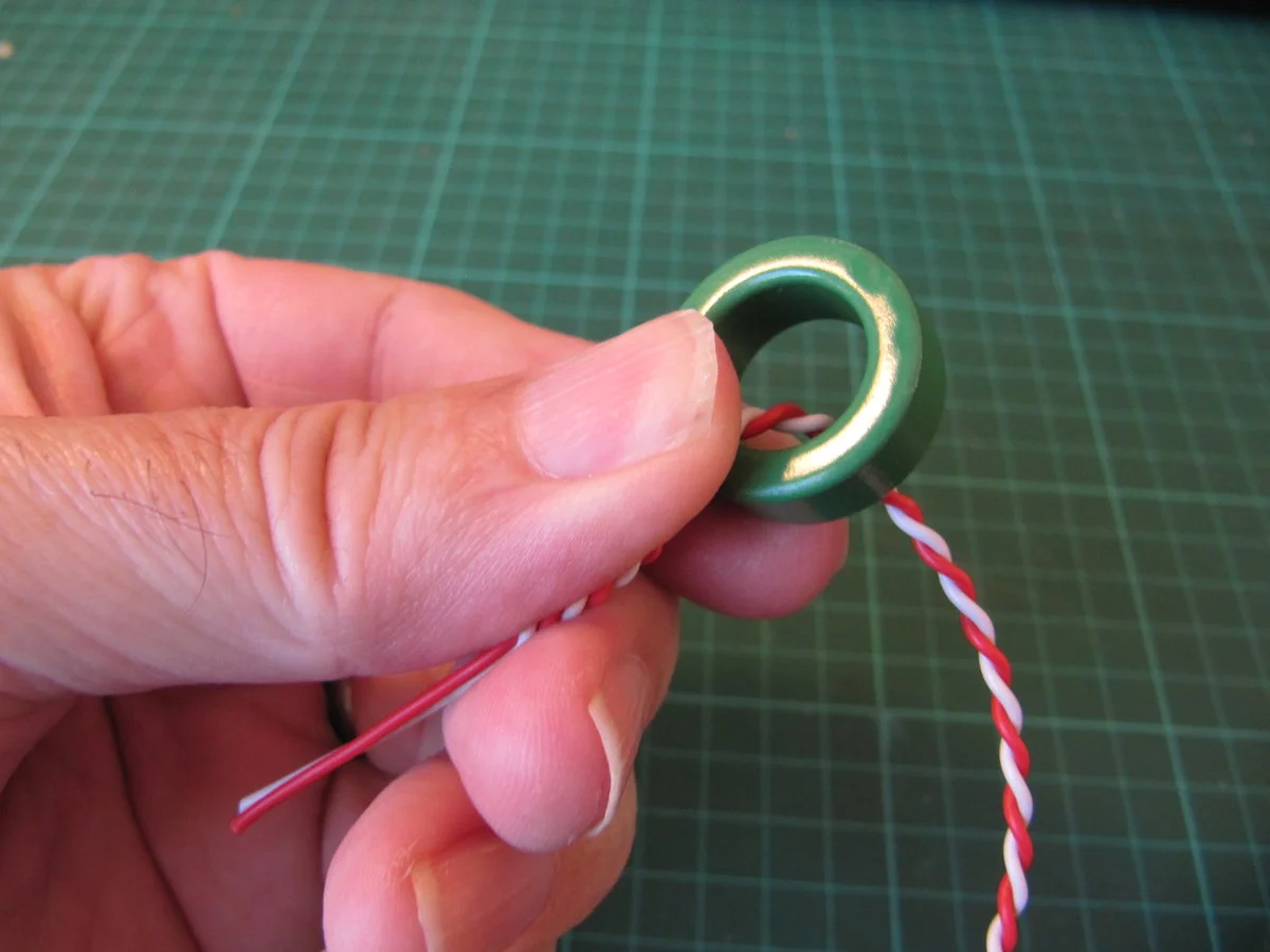
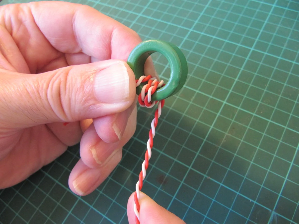
Hold that thought! More to the point, hold the pigtail; indeed, hold this pair of wires against the toroid using your left-hand thumb and finger. Don't let go of the pigtail wire and keep this pushed against that toroid.
Step twelve#
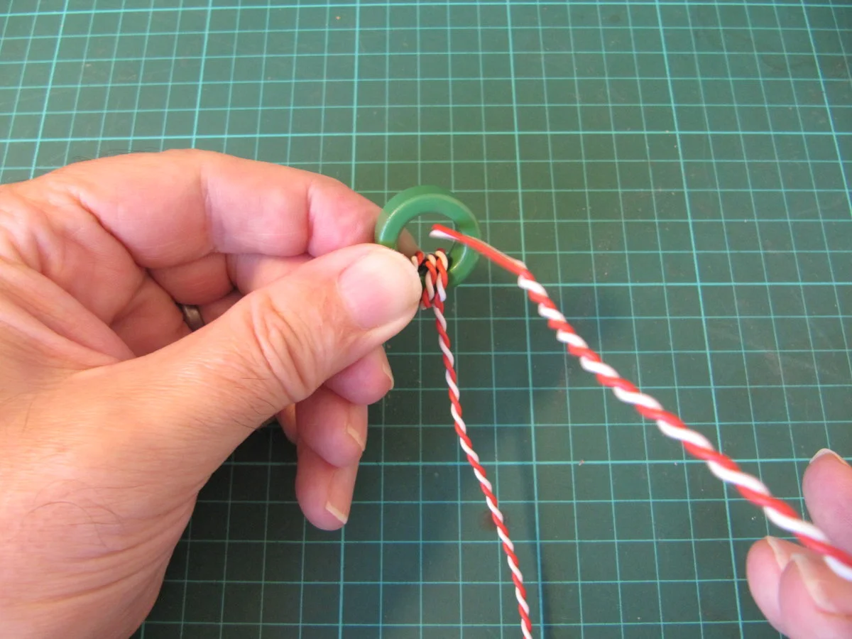
The free end must now be passed DOWN through the toroid. This is the correct manner with which to wind your toroid.
Step thirteen#
This counts as 2 (two) turns. We must continue winding. It may seem strange if you have never done this before, but with practice you get used to the feeling and the whole process.
Step fourteen#
This counts as 3 (three) turns. You must continue winding. You keep passing the twisted pair DOWN through the toroid.
Step fifteen#
Just keep winding.
Step sixteen#
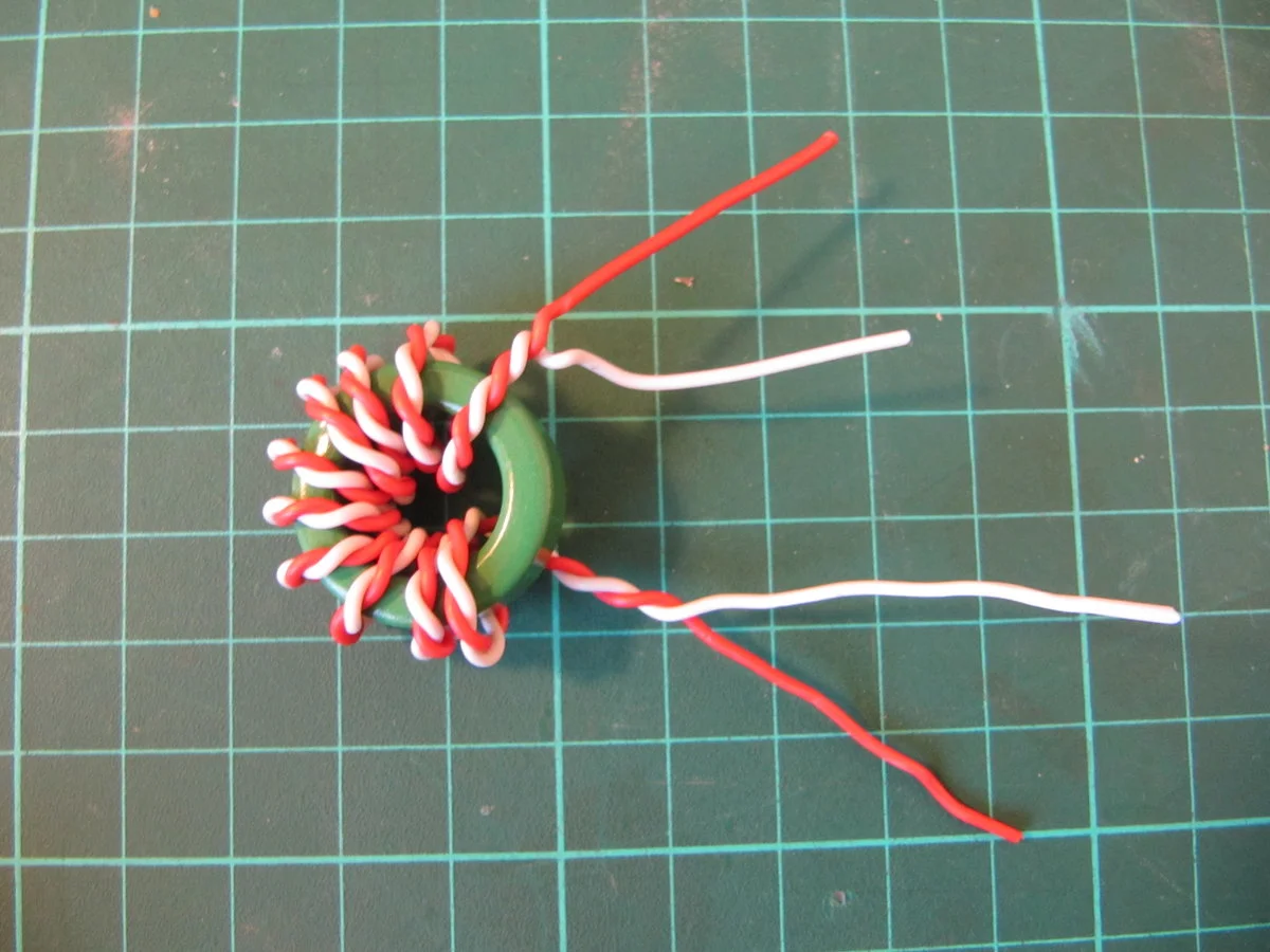
You now have 10 windings. This was the objective, which you now have achieved.
Step seventeen#
The windings must be distributed evenly. You must arrange the windings so that they are evenly distributed around the toroid. This process cannot be overstressed. However, don't get stressed about this, just do it.
Step eighteen (optional)#
If you have an LC meter, it's time to measure. You can measure the value of one of these windings using an L/C meter. Note that this toroid will show different results than your black FT50- 43 which is wound with solderable enamelled copper wire. To accomplish this, you find a pair of wires of the same colour. (With enamelled copper wire you will have to take that enamel off using a candle to burn the enamel and then take off the charred residue using wire wool or emery paper.)
You don't need to worry about this when winding with plastic insulated wire.
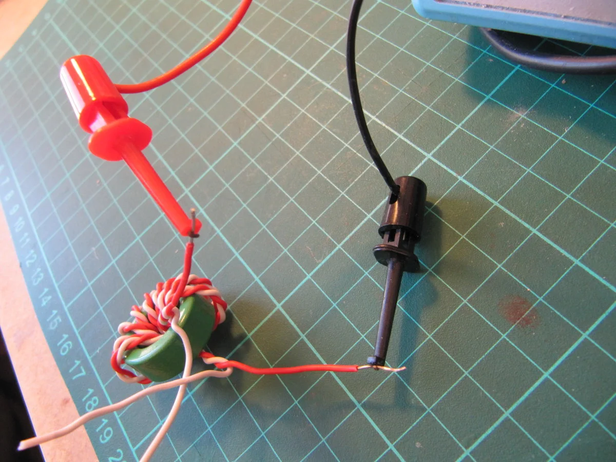
Step nineteen (optional)#
You might want to measure twice. This is always a good idea, especially with inductors.
Separate those wires and connect the windings to the L/C meter.
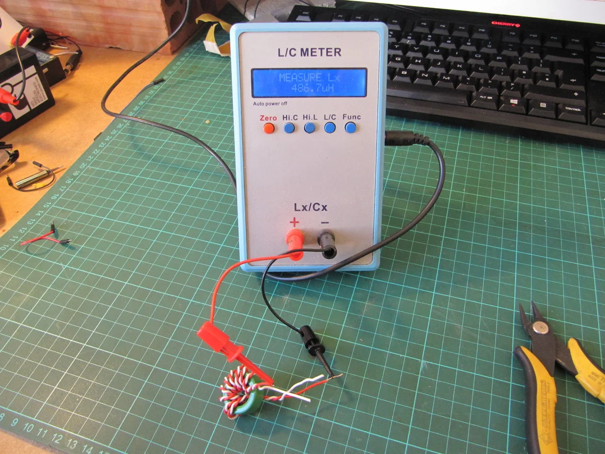
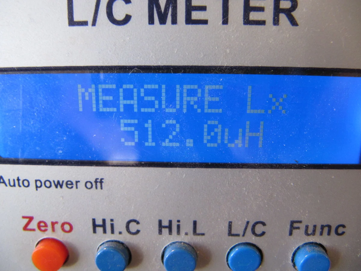
Step twenty-one (optional)#
With the green toroid with ten turns, the LC meter reads a value of 512 uH.
Measurement using an FT37-43#
Using the FT37-43, each winding of ten (10) turns should produce 35 uH.
- @ 3.5 MHz corresponds to an impedance of about 770 Ω
- @ 7 MHz corresponds to an impedance (Z) of about 1.5 KΩ
- @ 30 MHz corresponds to an impedance of about 6.5 KΩ
The above is just about sufficient for your transformer to work well over the entire HF spectrum.
Conclusion#
With these instructions, you should be able to wind a bifilar toroid. Please note that no L/C meter is entirely accurate. These meters, or measuring devices, operate in the kilohertz range, and this means that at RF, you may find that the authentic measurement is a little different. Nevertheless, they are useful, and you can pick one up at a reasonable price. The L/C meter pictured in the photograph is something I now don't use, as I bought myself a DE 5000; this is not low cost and is only really justifiable if you are serious about measurement.
Additional Notes#
-
Winding Direction: The direction of winding (clockwise or counter-clockwise) can be chosen based on your preference. This guide uses a counter-clockwise direction for consistency and ease of instruction.
-
Differences Between Enamel-Coated and Plastic-Insulated Wires: Enamel-coated wires require the removal of the enamel to ensure electrical connectivity, as the enamel acts as a thin, durable insulator. This typically involves heating the wire and then cleaning off the residue. Plastic-insulated wires, on the other hand, are visibly thicker and easier to handle. They do not require this treatment and the plastic insulation can be stripped off, and then used directly for connections. This guide assumes the use of plastic-insulated wires unless otherwise noted.
These notes are intended to assist users who are new to transformer winding and may not be familiar with some of the terms and practices mentioned in the main guide.